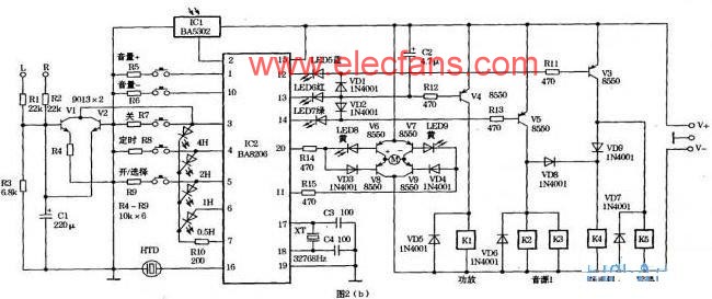
This circuit uses the easy-to-buy fan IC BA5104/BA8206 as the control chip. Through reasonable design, the function of the chip is maximized. After using the effect, it is introduced to everyone. It can achieve the following functions: This article refers to the address: http:// 1 manual / remote control; 2 volume remote control; 3 source selection; 4 delay shutdown; 5 switch machine speaker protection; 6 sound and light display. The principle of receiving and main control circuit is shown in Figure 2. IC2 is a fan circuit chip. This article describes its working principle as follows. 4. Delayed shutdown: Press the timing button after power on to make the delay shutdown time increase from 0.5-7.5 hours, LED1~LED4 are displayed accordingly. During the delay process, LED1~LED4 will be displayed in corresponding decrement, and all will be extinguished at the end, which is very intuitive. This feature is great for night use. The output wavefrom is pure sine wave, while the power of inductive load (such as refrigerator) is 6-10 times comparing to the normal continous usage. Pure Sine Wave Solar Inverter is designed by making reference to output waveform of mains power. The inverter can transform DC to AC ,so as to use high-ranking power electric appliances. Inverter Solar Power System,Pure Sine Wave Solar Inverter,Wave Inverter With Solar Charger,Sine Wave Solar Inverter Guangzhou City Poojin Electronic Technology Co., Ltd. , https://www.inverter-belttt.com
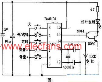
The principle of the transmitting circuit is shown in Figure 1.

1. Manual/remote control: According to the remote control button in Figure 1, the manual control/remote control is convenient for use.
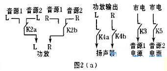
2. Sound source selection: Press the on/select button, IC2 pin 13 first outputs low level, so that red LED6 lights up for power-on display, and makes V4 turn on, K1 gets electricity, and the power amplifier is turned on. After 3 seconds, the 13th foot returns to the high level, the 14th foot turns to the low level, so that the green LED7 lights up as the sound source 1 is turned on, and V5 is turned on, so that K2 and K3 are electrically connected, and the figure 2 is turned on. Source 1 signal and power supply in (a). Due to the action of VD2, V4 is still turned on, so that K1 is connected to the power supply of the power amplifier. At the same time, through the VD8, the K4 is electrically connected to the speaker.
To use source 2, press the on/select button again, IC24 pin 14 returns to high level and pin 12 is low. The blue LED 5 lights up as the sound source 2 display, and makes V3 turn on, K5 is electrically connected to turn on the sound source 2 power supply, and then V4 is used to make the K4 pull-in and turn on the speaker. At this time, K2 releases the signal of the sound source 2, and K3 releases the power of the sound source 1.
To mute, simply press the On/Select button to make the red LED6 steady.
Because the BA8206 has a memory function, it will automatically resume the working state before the last shutdown when it is turned on next time. For example, before listening to the sound source 2, the next time the power is turned on, the 13th pin is low level, and after 3 seconds, the 12th foot is turned to the low level to turn on the sound source 2, which is convenient to use without having to reselect the sound source every time the power is turned on. .
3. Volume remote control: In Figure 2b, the 20th and 11th pins of IC2 are independent two bistable output terminals. When the volume is adjusted, press the volume + button, IC2 pin 20 outputs low level, so that V8 and VD3 are cut off. LED8 lights up for display and turns V6 on. The power supply V+ is increased by V6, volume motor M and V9 to the power supply V-. If you press the volume-key, the 11th pin of IC2 is low, so that V9 and VD4 are turned off, LED9 is lit for display, and V7 is turned on. Power supply V+ via V7, volume motor and V8 to power supply V-. Reverse the motor to achieve volume reduction.
The above volume is adjusted to the appropriate size. You need to press the volume + or - button again to return the 20th or 11th foot to the high level. Normally, V8, V9, VD3, and VD4 are all turned on. Because V6 and V7 are cut off, the volume motor stops without passing current. 
5. Switching the airport sounder protection: Every time the power is turned on, the 13th pin of IC2 always outputs the low level to turn on the power of the power amplifier. After 3 seconds, the selected sound source 1 or 2 is turned on again, and the K4 is connected to the speaker. It avoids the current impact on the speaker when it is turned on. When the power is turned off, the 12th, 13th and 14th feet are simultaneously high level, but due to the action of VD1 or VD2, C2 is charged to a low level, so that V4 is still turned on, so that the power amplifier is turned on, at this time, the sound source 1 or 2 and the speaker Disconnected, also avoiding the current impact on the speaker during shutdown. According to the capacitance value of C2 in the figure, after 4 seconds, V4 is turned off and the power supply is turned off.
Protection circuit: After the voltage is output from the midpoint of the power amplifier output, the voltage is divided by R1, R2 and R3. When the positive or negative bias of the power amplifier reaches 2V, V1 or V2 is turned on, and the third leg of IC2 is turned off to protect the ground. .
6. Sound and light display: The various control functions in the figure have corresponding LED display. It has been introduced above. At the same time, HTD will beep, very intuitive.
IC1 in Fig. 2b is an infrared receiving head, and the LED in Fig. 1 is used as a button remote control emission display. All color LEDs are selected with 3mm high brightness LEDs. 